

Getting Started with Hardware Hacking Using Raspberry Pi Zero 2W for Beginners
- BugFox Security
- Jul 5
- 5 min read

Hardware hacking often seems like a complex field reserved for experts with expensive tools. Many beginners hesitate because they believe they need costly programmers and debug kits to get started. The truth is different. The Raspberry Pi Zero 2W offers an affordable, compact, and capable platform to explore hardware hacking without breaking the bank. This guide will walk you through the basics of using the Raspberry Pi Zero 2W for hardware hacking, focusing on SPI, I²C, UART, and JTAG/SWD interfaces. You will also find practical advice on pinouts and tool installation to help you begin your journey confidently.

Why Choose Raspberry Pi Zero 2W for Hardware Hacking?
The Raspberry Pi Zero 2W combines a small form factor with enough processing power to handle various hardware protocols. It supports SPI, I²C, UART, and even JTAG/SWD debugging with the right setup. This makes it an excellent choice for beginners who want to learn hardware hacking without investing in expensive equipment.
Key benefits include:
Low cost: The device is affordable, making it accessible for hobbyists and students.
Compact size: Its small footprint fits well in tight spaces and portable projects.
Community support: A large user base means plenty of tutorials, forums, and resources.
Versatility: Supports multiple communication protocols used in hardware debugging and interfacing.
Safety and Ethical Considerations
Before connecting your Raspberry Pi Zero 2W to any hardware, keep these safety tips in mind:
Check voltage levels: Confirm whether your target device uses 1.8 V or 3.3 V logic. Use level shifters if necessary to avoid damaging components.
Work on authorized hardware: Only test devices you own or have explicit permission to work on.
Use ESD precautions: Electrostatic discharge can damage sensitive electronics. Use grounding straps and anti-static mats.
Limit current: Use a current-limited bench power supply when possible to prevent accidental damage.
Following these guidelines protects both you and your hardware.
Preparing Your Raspberry Pi Zero 2W
Start by updating your system and enabling the necessary interfaces:
```bash
sudo apt update && sudo apt upgrade -y
sudo raspi-config
sudo reboot
```

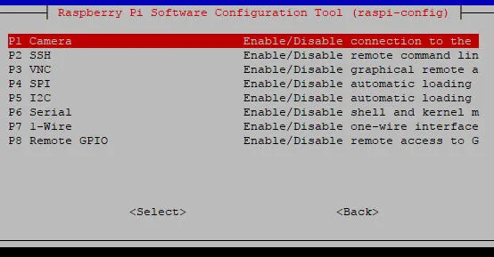
After rebooting, verify that the devices are available:
```bash
ls -l /dev/spidev*
ls -l /dev/i2c-*
i2cdetect -l
```
These commands confirm that SPI and I²C interfaces are active and ready for use.
Understanding the 40-Pin Header and Pinouts
The Raspberry Pi Zero 2W uses a 40-pin header with physical pin numbering from 1 to 40. When wiring, always reference physical pin numbers rather than BCM (Broadcom) GPIO numbers to avoid confusion.

Here is a simplified overview of important pins related to hardware hacking:
| Pin Number | Function | Description |
|------------|-----------|----------------------|
| 1 | 3.3V | Power supply |
| 2 | 5V | Power supply |
| 3 | SDA1 | I²C Data |
| 5 | SCL1 | I²C Clock |
| 6 | GND | Ground |
| 7 | TXD0 | UART Transmit |
| 8 | RXD0 | UART Receive |
| 19 | MOSI | SPI Master Out |
| 21 | MISO | SPI Master In |
| 23 | SCLK | SPI Clock |
| 24 | CE0 | SPI Chip Enable 0 |
| 26 | CE1 | SPI Chip Enable 1 |
Note that UART pins 8 (TXD0) and 10 (RXD0) are typically used for serial communication on the primary UART interface.
Working with SPI (Serial Peripheral Interface)
SPI is a fast, synchronous communication protocol commonly used to interface with flash memory, sensors, and other peripherals. The Raspberry Pi Zero 2W supports SPI through its hardware SPI pins.
How to Use SPI on Raspberry Pi Zero 2W
Enable SPI using `raspi-config` as described earlier.
MOSI (Pin 19)
MISO (Pin 21)
SCLK (Pin 23)
CE0 or CE1 (Pins 24 or 26)
Connect SPI devices to the following pins:
Install SPI tools for testing:
```bash
sudo apt install spi-tools
```
Test SPI communication by reading or writing data to your SPI device using appropriate commands or scripts.
SPI is ideal for reading flash memory chips or controlling devices like displays and ADCs.
Using I²C (Inter-Integrated Circuit)
I²C is a two-wire protocol used for communication between microcontrollers and peripherals such as sensors, EEPROMs, and RTC modules.
Setting Up I²C
Enable I²C via `raspi-config`.
SDA1 (Pin 3)
SCL1 (Pin 5)
Connect I²C devices to:
Install I²C tools:
```bash
sudo apt install i2c-tools
```
Scan for connected devices:
```bash
i2cdetect -y 1
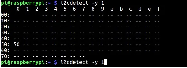
This command lists all devices connected to the I²C bus, showing their addresses.
Practical Example
If you connect a temperature sensor that uses I²C, you can read its data by communicating over the bus using Python libraries like `smbus`.
UART (Universal Asynchronous Receiver/Transmitter)
UART is a simple serial communication protocol used for debugging and communicating with serial devices like GPS modules or serial consoles.


Using UART on Raspberry Pi Zero 2W
The primary UART pins are:
- TXD0 (Pin 8)
- RXD0 (Pin 10)
Enable the serial interface in `raspi-config` under Interface Options.
Use terminal programs like `minicom` or `screen` to communicate with serial devices:
```bash
sudo apt install minicom
minicom -b 115200 -o -D /dev/serial0
```
```bash
sudo apt install picocom
Picocom -b 115200 /dev/ttyUSB0


UART is useful for logging data or interacting with microcontrollers.
Notes:
On Pi, /dev/serial0 is symlinked to the primary UART. /dev/ttyAMA0 or /dev/ttyS0 may vary by model.
Disable getty on the serial port if you need exclusive access: sudo systemctl disable --now serial-getty@ttyAMA0.service (replace device name as required).
JTAG and SWD Debugging
JTAG and SWD are hardware debugging protocols used to program and debug microcontrollers and processors at a low level.
Using Raspberry Pi Zero 2W for JTAG/SWD
While the Pi Zero 2W does not have dedicated JTAG pins exposed by default, you can repurpose GPIO pins for this purpose with additional hardware adapters.
JTAG requires multiple pins for clock, data, and control signals.
SWD uses fewer pins and is common for ARM Cortex devices.
Tool Installation
You can use open-source tools like OpenOCD to interface with JTAG/SWD hardware:
```bash
sudo apt install openocd
```
Configure OpenOCD with the correct pin mappings and connect your target device accordingly.
Practical Tips for Hardware Hacking Projects
Double-check wiring before powering devices.
Use breadboards and jumper wires for prototyping.
Label your connections to avoid confusion.
Start with simple devices like I²C sensors or SPI flash chips.
Document your setup and commands for future reference.
Conclusion
The Raspberry Pi Zero 2W proves that you don’t need expensive programmers or proprietary debug kits to begin exploring hardware security. With nothing more than a $15 board, some jumper wires, and free open-source tools, you can dump SPI flash, talk to I²C devices, access UART consoles, and even experiment with JTAG/SWD debugging.
This approach makes hardware hacking both accessible and practical for students, researchers, and security professionals. While the Pi’s GPIO interfaces are slower than dedicated programmers, they provide an excellent way to learn fundamentals, validate proof-of-concepts, and build confidence before investing in specialized hardware.
As you grow more comfortable, you can expand with tools like logic analyzers, level shifters, or professional JTAG probes — but the foundation remains the same: understanding protocols, making careful connections, and using the right software for the job.


Comments