

Hardware Interface Analysis: Leveraging UART for Shell Access on Linux Routers Tp-Link TL‑WR850N v3
- BugFox Security
- Jul 6
- 5 min read


Accessing the internal workings of a router can unlock powerful possibilities for customization, troubleshooting, and learning. The Tp-Link TL-WR850N v3 is a popular Linux-based router that offers a practical example of how hardware interfaces like UART can be used to gain shell access. This post explores the process of analyzing the hardware interface and using UART to connect to the router’s shell, providing a clear guide for enthusiasts and professionals interested in embedded systems and network hardware.
Understanding UART and Its Role in Router Access
UART, or Universal Asynchronous Receiver/Transmitter, is a hardware communication protocol that allows serial communication between devices. It is commonly used for debugging and direct access to embedded systems like routers. Many routers include UART pins on their circuit boards, which provide a direct line to the device’s console.

Using UART to access the shell on a router means connecting to the router’s serial console. This connection allows you to interact with the router’s operating system directly, bypassing network interfaces and web-based management tools. This method is especially useful when the router is bricked, locked, or otherwise inaccessible through normal means.

Tp-Link TL-WR850N v3

Component Identification & Recon
Before diving in, I spent some time exploring the board visually and via datasheets to understand what we’re troubleshooting:
SoC: The heart of the router is the MediaTek MT7628NN, a 32-bit, 575 MHz MIPS CPU with integrated DDR RAM controller, Ethernet, Wi-Fi, UART, SPI, and more. The OpenWRT dev forum confirms this is the active SoC for v3 hardware.

RAM / Flash: 32 MB of SDRAM and 4 MB NOR flash — pretty standard for this class. The flash contains U-Boot, kernel, and squashfs rootfs.


UART Interface: A 4-pin header silkscreened as J1, clearly labeled [VCC] [TX] [RX] [GND] — so someone intended for UART access conditional on not populating the header.

Logic Traces: The TX/RX lines go directly to the MT7628’s UART pins (likely UART0, pins GPI0/GPI1 exposed). No ESD diodes or level shifters — pure 3.3 V logic.
Other Components: A 40-pin SPI flash is nearby, useful later for direct dumping if UART is blocked. Also, U-Boot version 1.1.3 from 2019 (seen in logs) gives clues about available features and security posture.
This level of recon — visual, datasheet, and community-based — is critical. It tells us what tools, protocols, and approaches will work (and what won’t), without risking hardware damage.
Step 2: Verifying UART Voltage & Signal with Multimeter & Logic Analyzer
a) Voltage Check with Multimeter
1. Set your multimeter to the DC volts range (~0–20 V).
2. With the router powered on and Tigard unplugged:
Place the black probe on a known ground (e.g., Ethernet shield).
Touch the red probe to the suspected VCC pad on the header.
3. Observe the reading:
~3.3 V confirms it’s a TTL-level UART (safe with Tigard).
~5 V means the board expects RS232 or different voltage — use caution!
4. Confirm ground: switch to continuity mode and touch black on known ground; red to each pad. Buzz indicates ground.
This multimeter method is exactly what debug experts recommend for identifying TX/RX/VCC/GND pads on PCBs before probing with logic tools.
b) Verifying UART via Logic AnalyzerNow check that TX/RX are real UART signals:
Connect your logic analyzer (like Tigard’s LA port or an external analyzer) to:
GND probe → router ground
One channel probe → router’s suspected TX pad
2. Power on the router and start capturing at a sample rate ≥ 230 kS/s (4× the target baud rate).
3. Use PulseView or its CLI:
Add a “UART/Async” decoder.
Try baud rates: 57600, 115200, 38400.
4. If it’s genuine UART, you should see nicely decoded ASCII boot logs (e.g., U‑Boot…, Linux kernel messages).
A classic UART pattern: idle high, bursts of activity during boot, decoded data reads clean. If not, flip probes between TX and RX.
Step 3: Connecting the Tigard (FT2232H-Based Tool) for UART Shell Access
This section dives into how to reliably connect your Tigard tool to the TL-WR850N v3’s UART interface — no guesswork, just practical steps backed by the actual Tigard spec and real user experience.

a) Why Tigard is a Great Fit* Built around the FT2232H, Tigard offers dual ports:
Port A is fixed as UART (for console access).
Port B can switch between SPI, I²C, SWD, or JTAG via the MPSSE. This means you can reuse it later for SPI flash dumps or JTAG debugging.
Voltage flexibility (1.8 V to 5.5 V) with a switchable VTGT pin — critical for safely matching target voltage.
Clear labeling and harnesses: UART Tail harness includes GND, TX, RX, and optional VTGT. No accidental miswiring.
LED indicator for TX/RX activity ensures signal presence even before your terminal loads.
b) Step-by-Step Hardware Setup
1. Switch Voltage
Set the Tigard voltage selector to target the router voltage (“VTGT” mode), which allows level-shifting to 3.3 V.
2. Wire Connections
Plug the UART Tail harness onto the Tigard header:

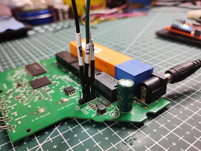
Tigard GND ↔ Router GND Tigard TX → Router RX Tigard RX ← Router TXLeave VTGT (pin 1) disconnected unless you intend to power your target from Tigard. It only senses voltage once connected.
3. Driver & Device Recognition
Connect via USB‑C. Two devices will appear: the first UART port is for console. On Linux it’s typically /dev/ttyUSB0.
4. Terminal Configuration
Launch your terminal with:
picocom -b 115200 /dev/ttyUSB0
Or:
minicom -b 57600 -D /dev/ttyUSB05. Powering the Router
Plug in the router’s power supply. If wiring is correct, boot logs should display immediately. Tigard’s LEDs will flash during UART traffic for visual confirmation.

c) Real-World Tips & Troubleshooting* If no output appears, confirm:
Voltage selector is set to VTGT/3.3 V, not 5 V.
Ground is correctly shared (common GND is essential).
You connected the correct harness — the UART Tail has colored wiring and labels (black = GND, green = TX, white = RX).
If you see scrambled characters, try alternate baud rates like 115200 or 38400 — but 57600 is standard for MediaTek-based TP-Link routers.
No RX (can’t type input)? It could be disabled in hardware:
some routers include a pull-down resistor or trace cut on RX to block input. You may need to remove or replace this resistor to enable read/write shell.
Step 4. Gaining Shell Access
You hit a key milestone: UART shell login credentials were activated and allowed you full shell access. Here’s exactly how that works and what it means:
A. How admin:1234 Appeared
Once the router booted, I was greeted with a login prompt over UART:
TL-WR850N login: admin Password: 1234
What’s Next?
Now that I have a shell, these are my options:
Privilege Escalation
Look for misconfigured scripts or crons
Check if any running services can be hijacked
Try memory/heap fuzzing of binaries
2. Firmware Dump (Offline)
Use Tigard in SPI mode to dump firmware
Reverse engineer for root credentials or backdoors
3. Runtime Binary Injection
Upload static BusyBox or other binaries via netcat
Drop tools into /tmp and run from RAM
4. Network Pivoting
If the router is connected to other devices, scan the LAN
Use it as a pivot point for broader testing (assuming legal context).


Comments